Mini FRC Robot
Makerspace 1 - Mini FRC Robot
In my first makerspace I attempted to create a robot using old FRC components. I programmed the robot to move around in any direction based on driver input. The robot ultimately was not able move because I ordered the wrong belt size so I was not able to put them on.
Making the chassis:
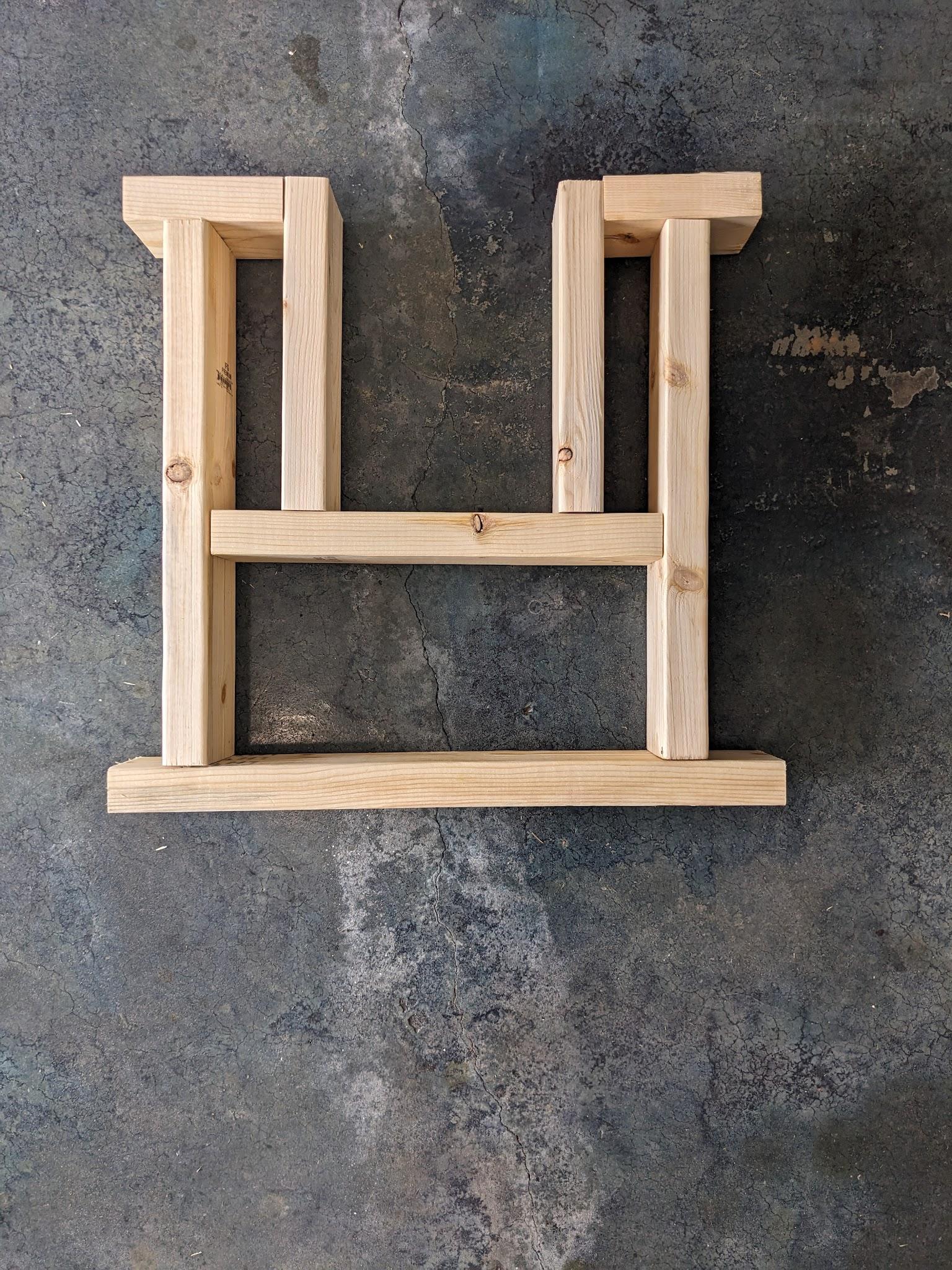
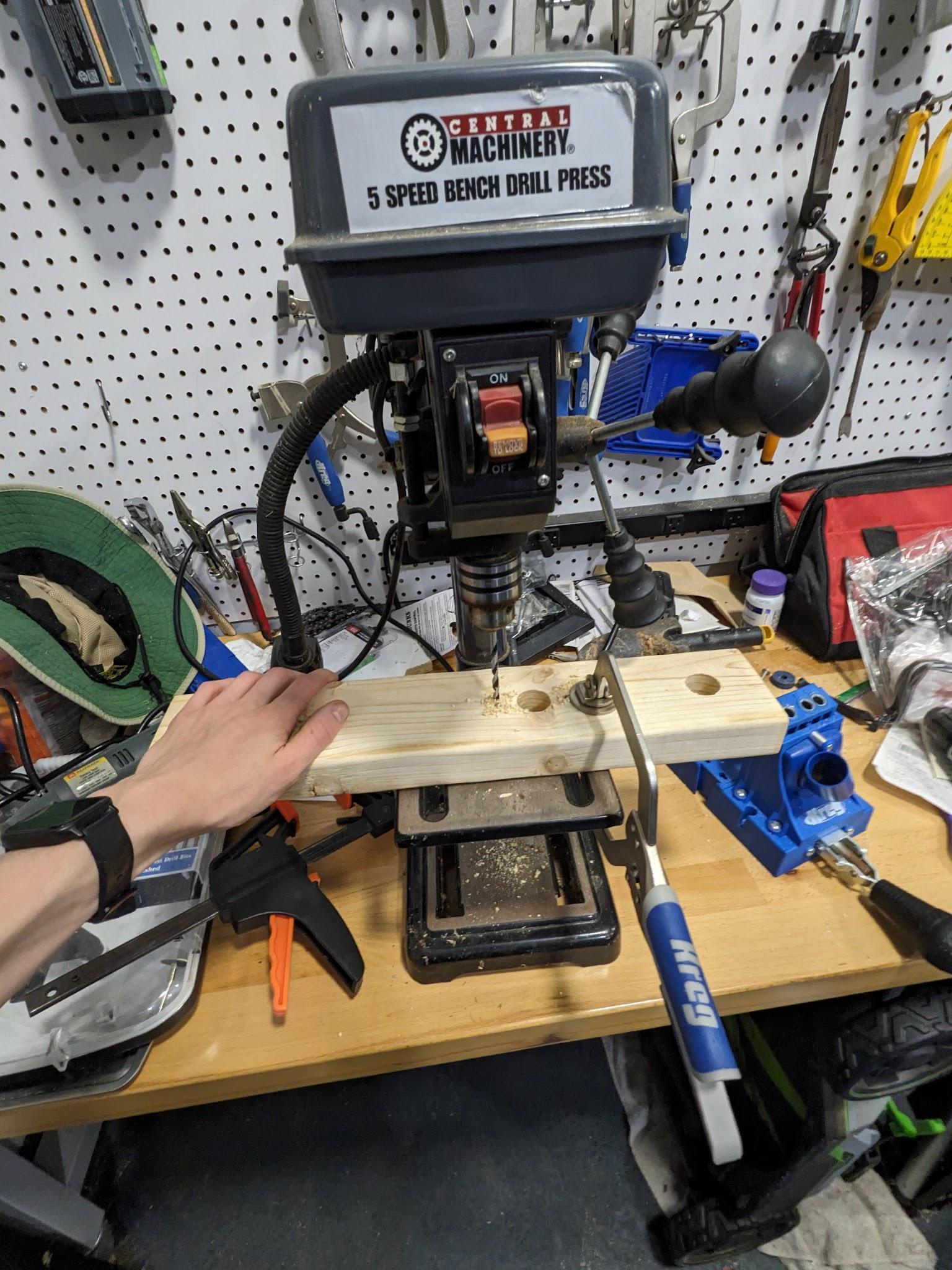
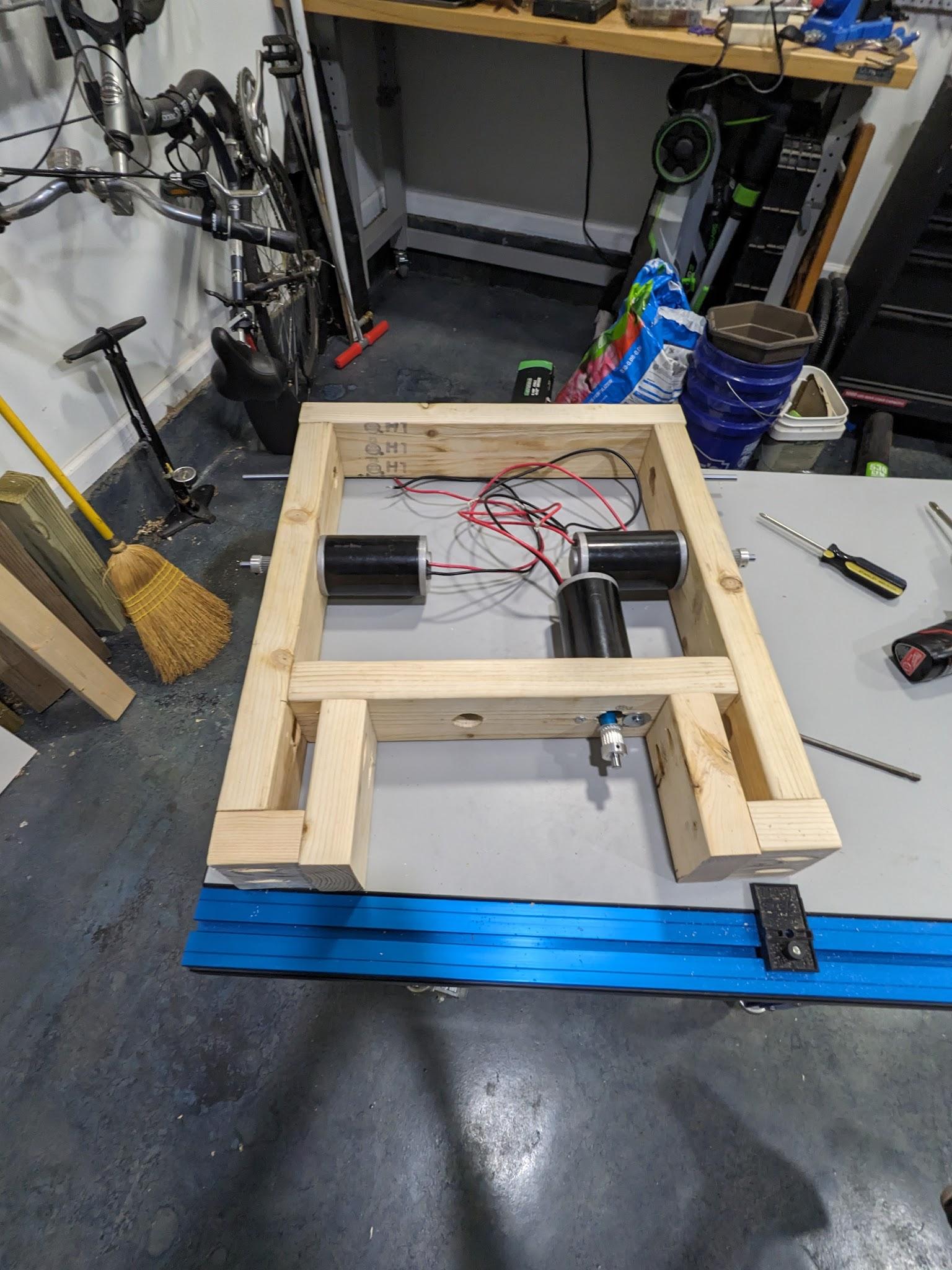
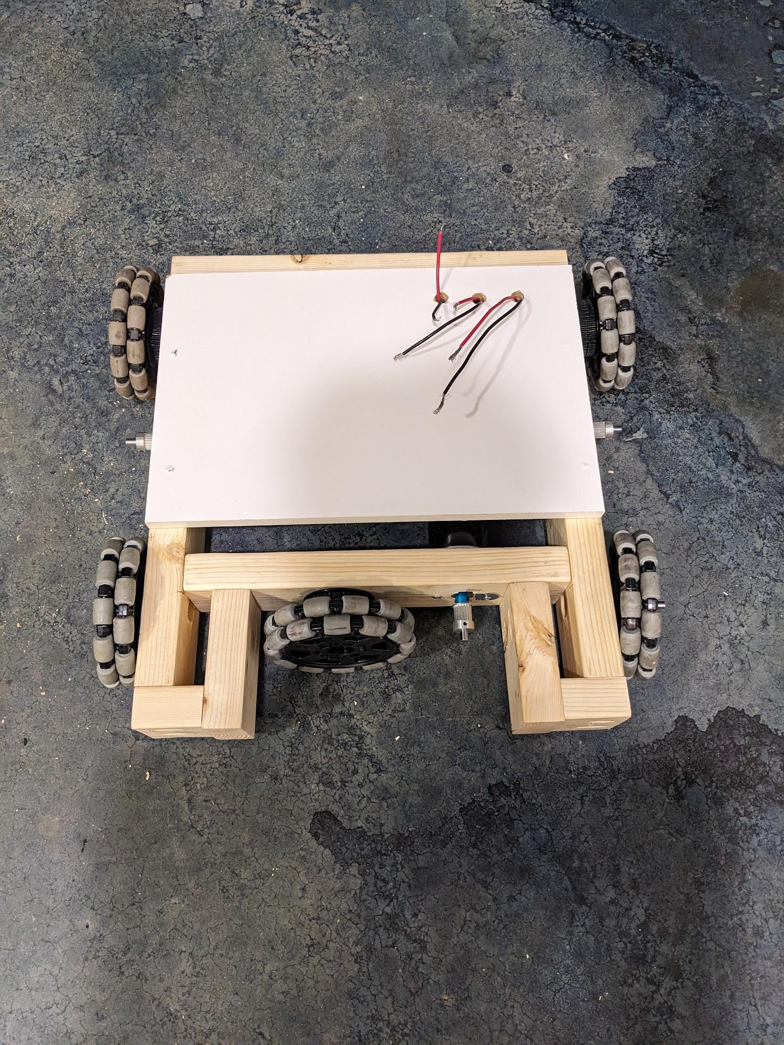
The chassis was made with 2x4s and held together with pocket screws. On the right was my ‘first draft’ for the chassis. To get to the final one, I cut off any wood off the edge and moved the middle 2x4 toward the front.
Electronics:
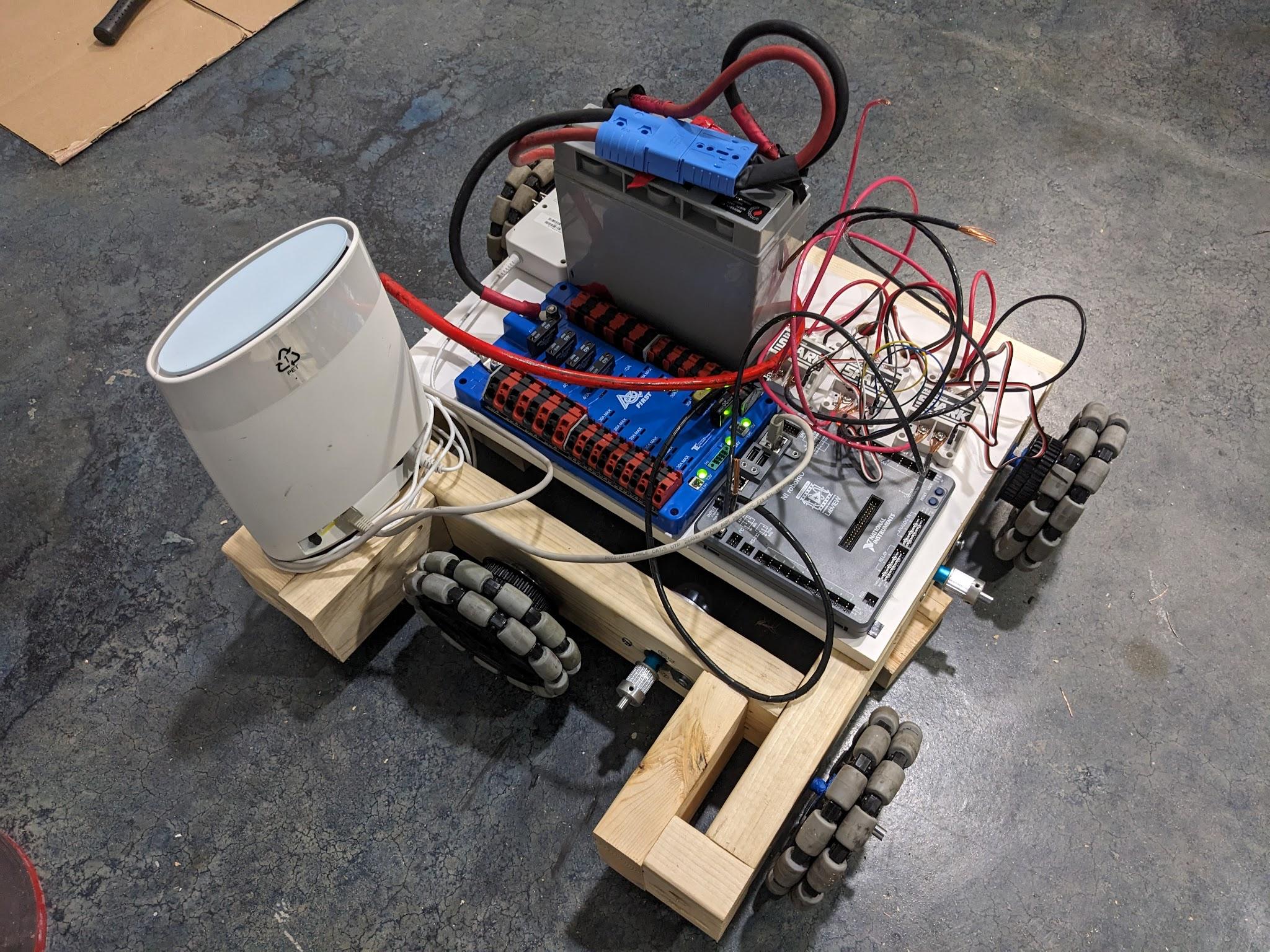
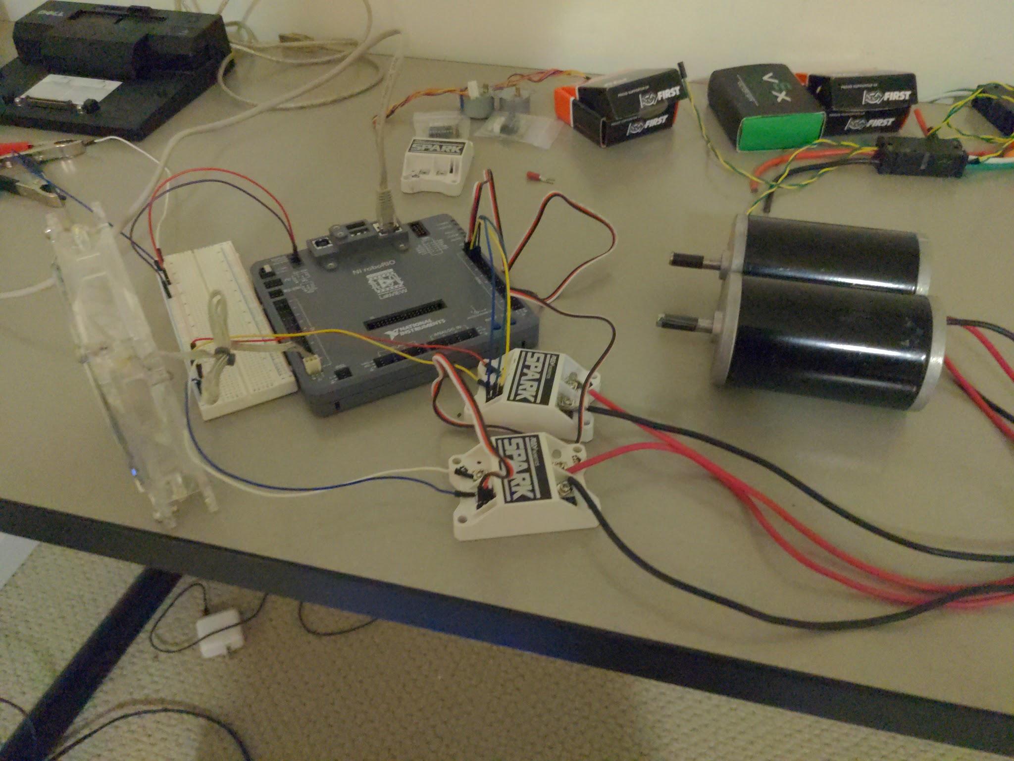
I used a roboRIO as the brains of my robot. This is the same controller that is used in FRC robots. I used spark motor controllers with CIM 300W motors. The spark motor controllers are connected to the roboRIO via PWM wires. The motor controllers are powered by the power distribution panel (PDP), giving power from the battery. To control the roboRIO, I connected it to a Wi-Fi router via ethernet. (When this didn't work I connected it directly to the drive computer.) I set up a computer with driver station software and, using a Xbox controller, controlled the robot.
(The 28 gauge wire was just for testing.)
Code:
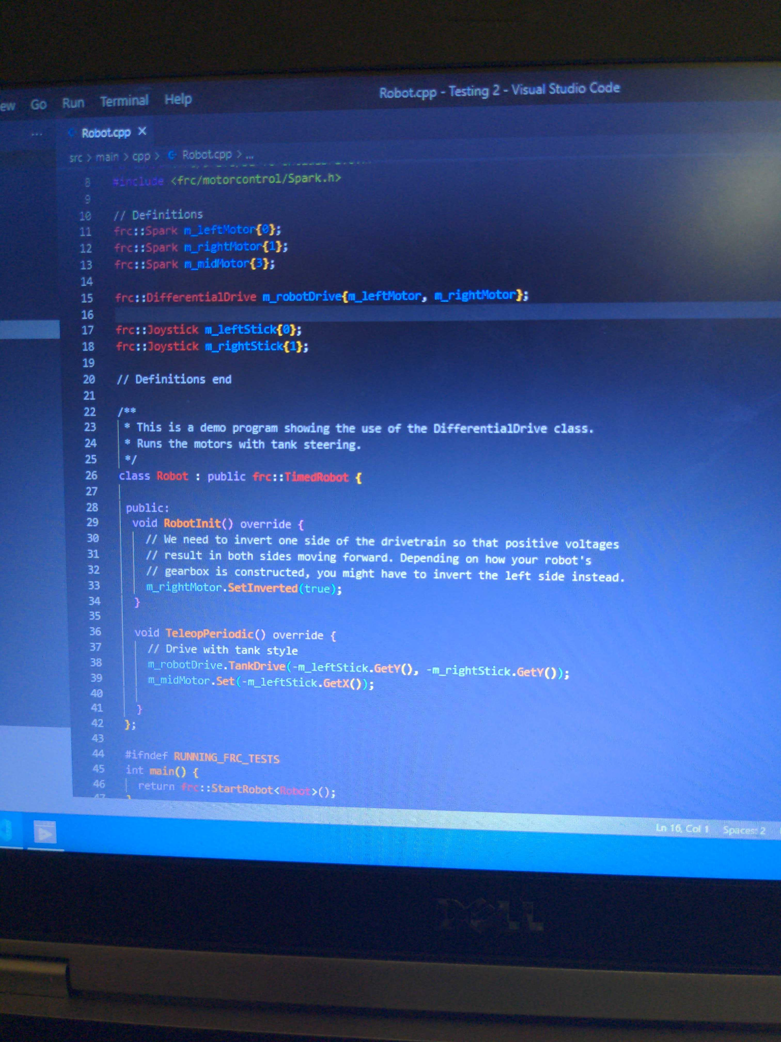
I only have this one picture remaining of the code because of software difficulties. It takes in Joystick positions and calculates the outputs for the motors.
The left joystick moves the robot forward, backward, left and right while the right joystick rotates the robot.
This was a test of the motors and the code.
Because I was using a simple wall power supply for power, the motors could easily brown out, causing them to stop. This did not happen in this test though. Using the more powerful robot battery, this will not be an issue.
Photonvision :
I was hoping to include vision tracking into the robot. (Next section for why I didn't) The test I did for photon vision is shown in the video. This would allow the robot to identify targets around it and pick up targets autonomously.
Software Issues:
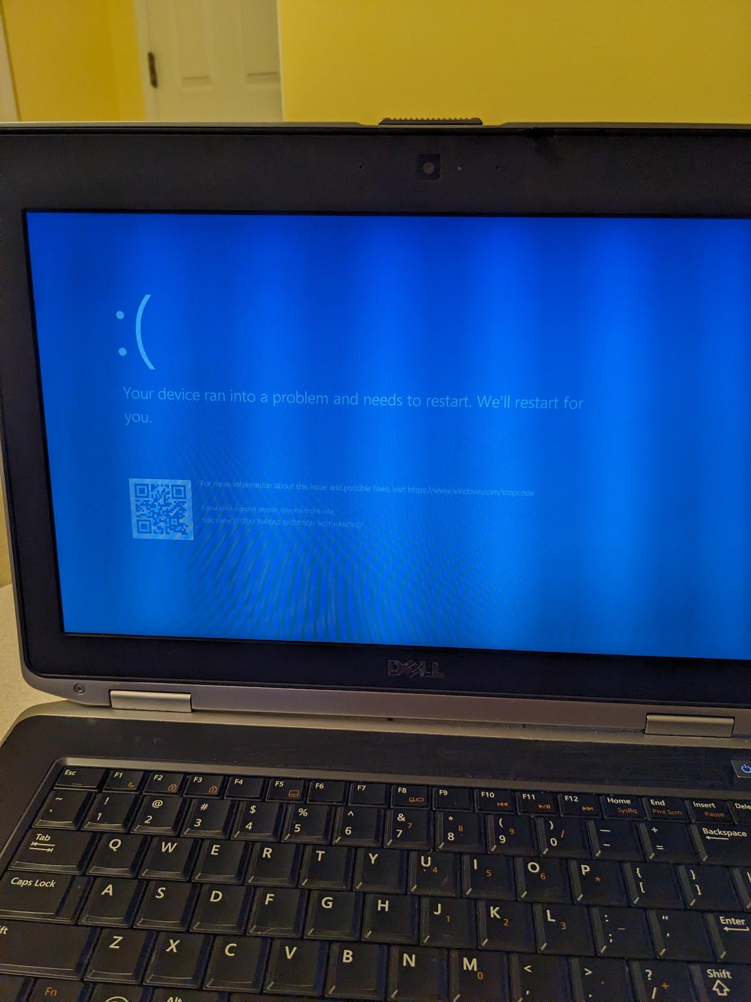
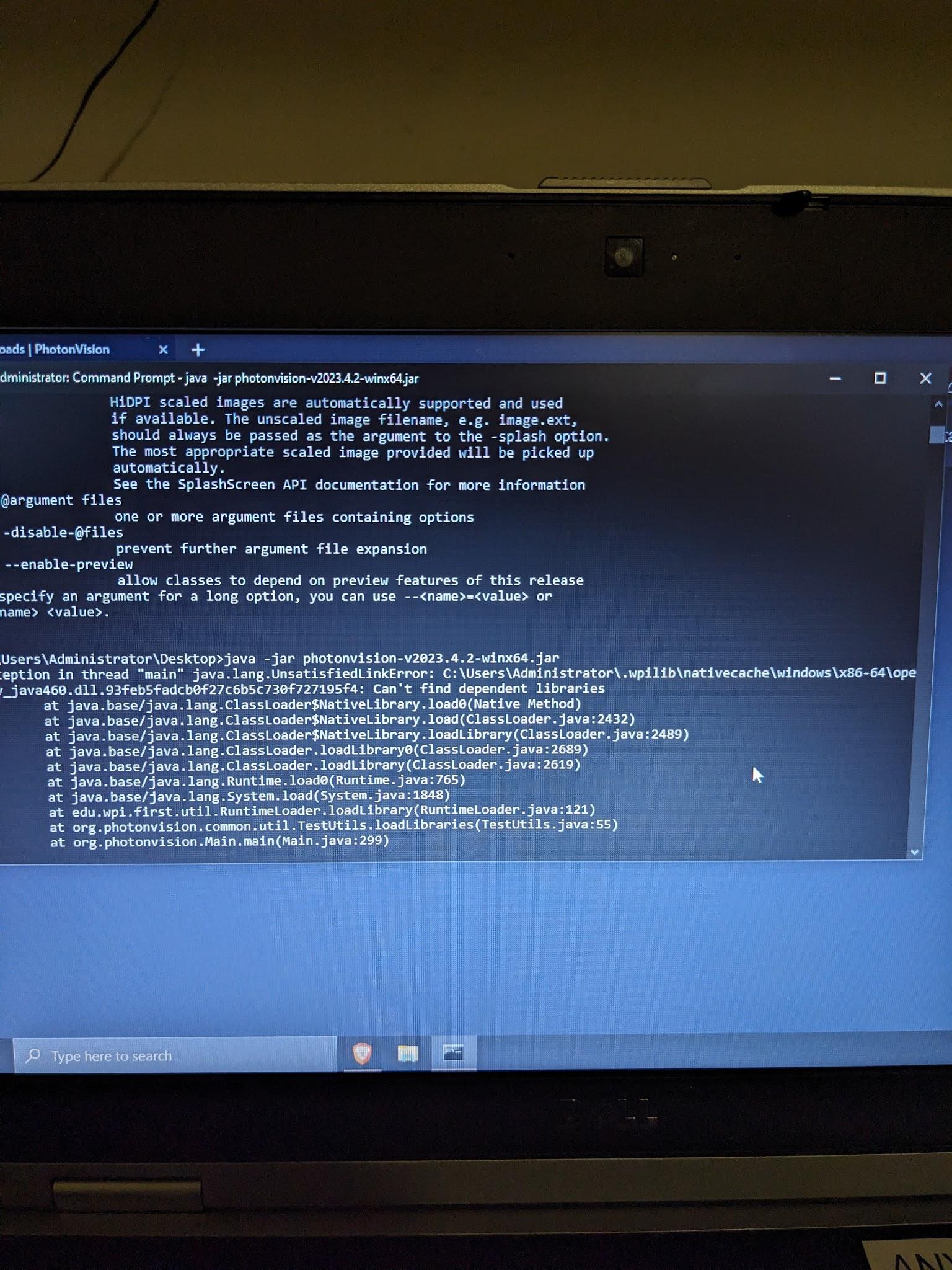
Due to some software difficulties, the computer used for photonvision and the code broke itself. I may be able to recover some files from a linux installation on the computer but for now I am stuck with whatever code is present on the roboRIO already. Silly me didn't back up the code… Attempting to run photonvision on a different computer gives the error on the right. I am not sure what is causing this but it means I will not be able to include photonvision for a while.
Frame Together:
When I attached the wheels, the bearings, despite being the ‘perfect size’ would slip out of the mounting holes. Painters tape saves the day! Just a little bit of painters tape made the bearings nice and snug where they were supposed to be. I screwed bolts into the motors to attach them to the chassis. I then placed a board across the top of the chassis to mount the electronics, with holes for motor wires.
Put Together:
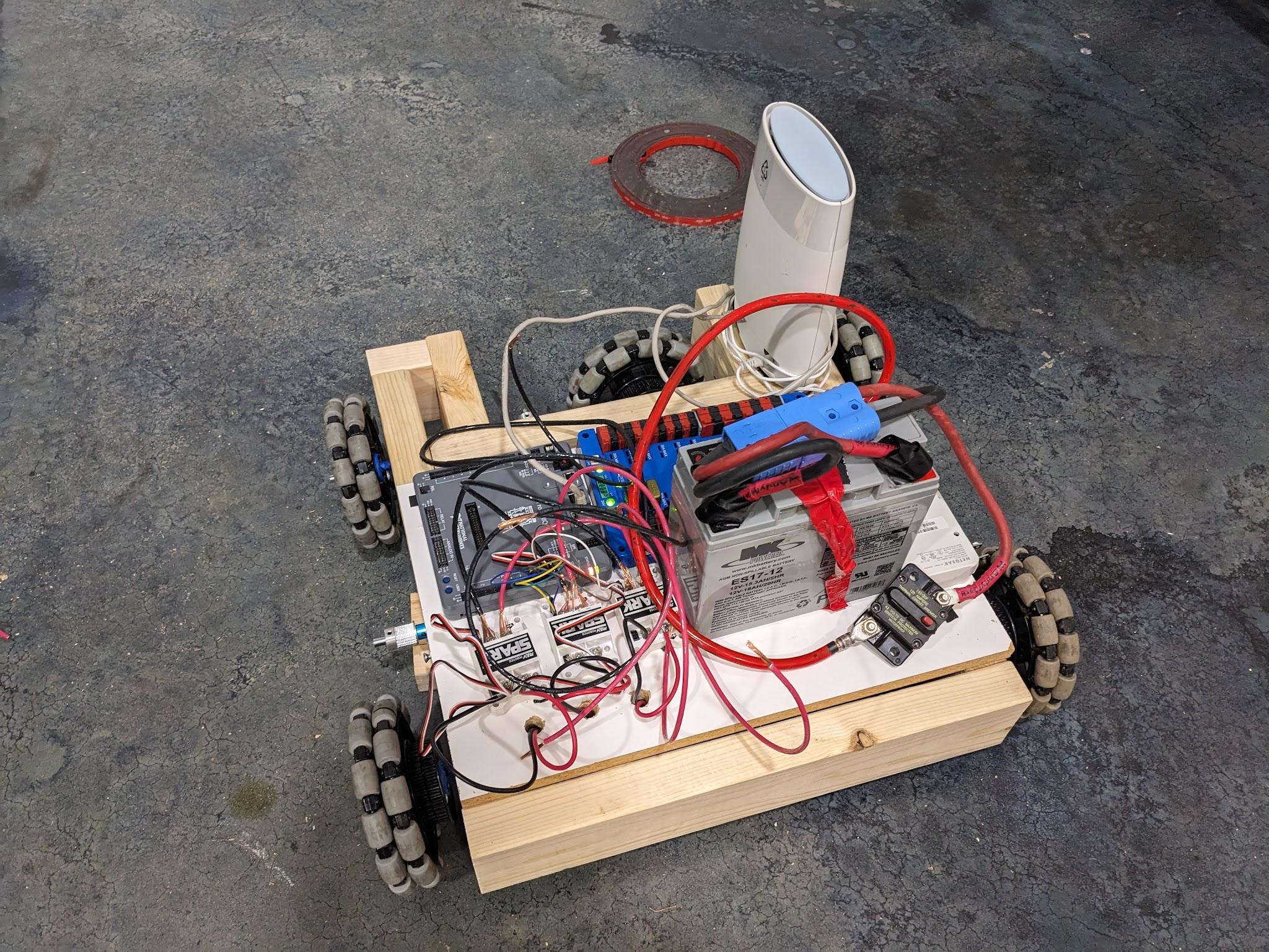
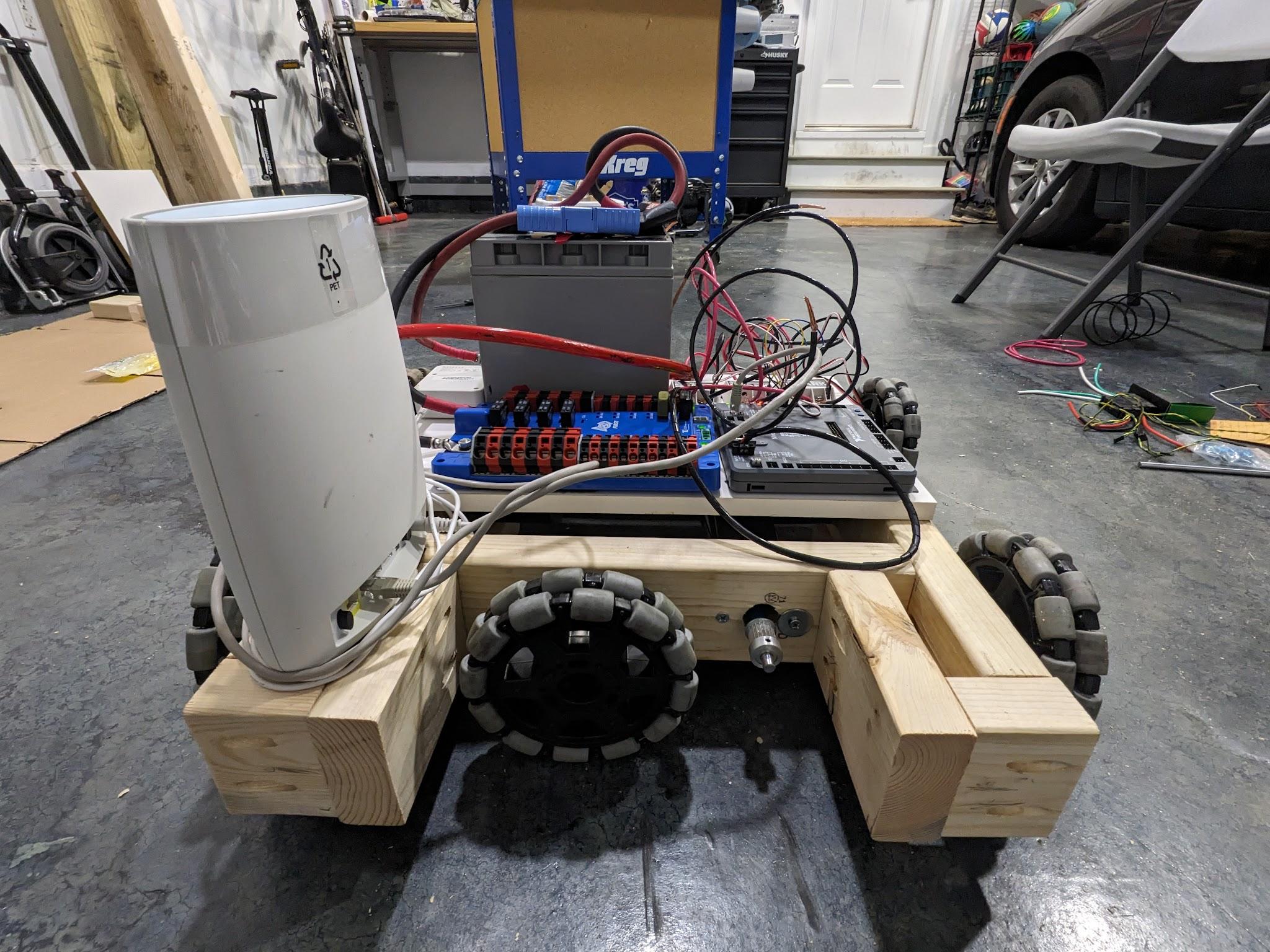
All the electronics were put onto the chassis with vcb and wired together.
At this stage I forgot how to operate the power distribution board to put the motor controller wires into it, so they were not attached at this point.
During this time the wheels could not stay straight because I did not have spacers printed. This was because the only 3D printer available was one where the previous person had clogged the 3D printer. (With the spacers printed the wheels would be straight.)
Final Touches:
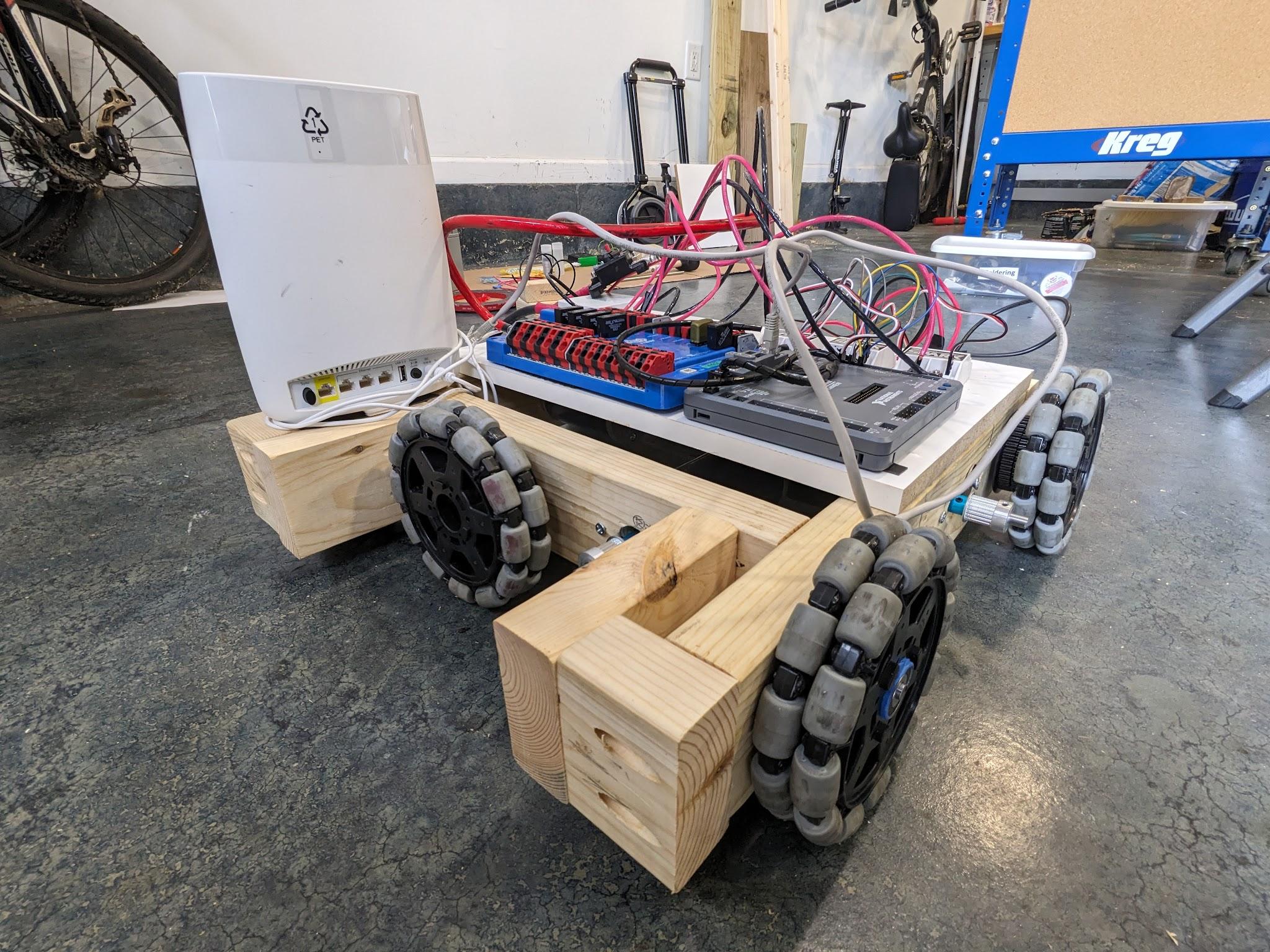
Added 3d printed spacers to help support the wheels. These worked even better than I thought they would.
The robot is now lifting its own weight with the wheels without bending.
I figured out how to plug in the motor controllers to the power distribution board.
Here is the first test with everything put together. (Excluding the belts and router.)
Final Words:
The old Wi-Fi router did not work because I did not have a spare power cable I could sacrifice for the project and the power brick would not accept 12v. Additionally, the belts did not arrive in time for the due date, so the robot could not move the wheels. (When the belts did arrive later they were the wrong size.)
